Operating instructions for the 6957 automatic block base unit.
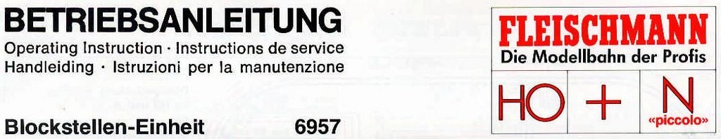
The basic unit of the FLEISCHMANN 6957 automatic block consists of:
an A transformer connection piece, 3 coupled block relays and a V interconnection plug (fig. 1). This unit is used to connect 3 block sections and can therefore be used to run 2 fully protected trains at the same time on the same line.
Connection and operation.
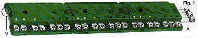
Fig. 2 shows the principle wiring of the 6957 base unit for HO and N gauge trains when using 6425/6435/9425 track contacts and 9426/9427 magnets. In a track oval, we start by dividing one of the rails into 3 separate blocks forming stop sections H1, H2 and H3. This is done using 3 x 2 'insulating clamps 6403/6433/9403. The length of the stop sections must be calculated in such a way that a locomotive can stop there without passing them on its way. Full-track sections B1, B2 and B3 must be longer than the longest train expected to run on them. Each block is supplied by 2 wires coming from the corresponding relay, a blue wire going to the stop section and a yellow wire going to the adjacent full track section, immediately after the sectioning.
The control contacts are connected to their relays by means of 2 white wires (represented by dashes).
dashes). The yellow, white and black terminals on connection part A are connected to the same-coloured terminals on the transformer.
same colour on the transformer. The second yellow terminal of the transformer is connected to the rail opposite the one
which contains the isolating devices (terminal block K). To operate the block relays
use 3 track contacts 6425/6435/9425 operated by magnets 9426 usually fixed to the last car of the train, or
of the train, or better still under the locomotive.
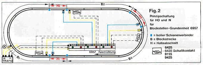
Fig. 3 a - d shows 4 practical ways of sticking the magnets under the wagons.
Fig. 3 a, b Fig. 3 c, d
Fig. 3 Attaching magnets 9426/9427 to HO wagons :
a) bogie wagons: in the middle of a bogie.
b) axle wagons: fixed in the middle of the underframe.
Attaching magnets 9426/9427 to N wagons:
c) bogie wagons: next to the bogie and offset to the side where the track contact is located.
d) wagons with fixed axles: in the middle of the chassis but offset to the side where the track contact is located.
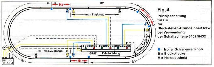
Fig. 4 shows a wiring diagram similar to Fig. 2, in which a contact rail is used in conjunction with the contact head attached to the underside of the locomotives.
6402/6432 contact rail is used in conjunction with the contact mushroom mounted on the underside of the locomotives.
In this case, particular care must be taken to ensure that the 6402/6432 contact rail is positioned after the shutdown disconnecting
a minimum distance corresponding to the longest train planned. In addition, it is also necessary that the
also be made in the right-hand rail in the direction of travel.
To start up the system, first press all the red relay buttons while the
the 2 trains are each in a different block. Then open the transformer regulator
regulator, making sure that the direction of travel is correct, and press the green button on the relay corresponding to the unoccupied block.
unoccupied block. The block sections then automatically protect themselves.
Connection
Possible connection of signals.
Fig. 5 shows the same diagram as fig. 2, with the addition of the connection of illuminated stop signals
6226/9225 or paddle stop signals 6205/9205. Simply connect the wires
the black, green and red wires of the signals to the corresponding coloured terminals of the block relays.

Manual intervention possible.
The position of each of the relays can be controlled by their push buttons: red button pressed = stop; green button pressed = free track.
stop; green button pressed = track free. The movement of trains can therefore be controlled by pressing the
corresponding button.
Increasing the number of blocks.
The basic automatic block group can be expanded by adding one or more block relays.
6958, i.e. one relay for each additional block. To do this
first remove the V interconnection plug and transfer it to the last 6958 relay (fig. 6).
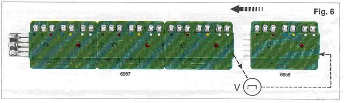
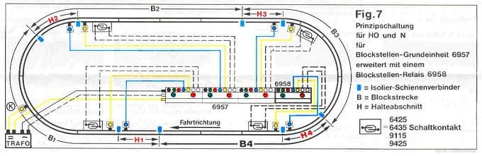
Fig. 7 shows how to incorporate an additional 6958 relay between the existing 2 blocks.
Here is a brief summary of the advantages of the FLEISCHMANN automatic block:
1, Possibility of block-by-block expansion by simply incorporating a 6958 block relay.
2, Connection of signals provided from the outset.
3. Possibility of running trains with interior lighting.
4, The slowest locomotive runs the entire circuit without stopping.
5. The control of each block is visually controllable at the relays and leaves the option.
to intervene manually.
6. Can be used for all types of trains as the system is independent of locomotive engine consumption.
consumption of locomotive engines.
7. Possibility of incorporating 6954(*) retarding resistors.
8. Relay consumption: only 50 mA.
(*) Not suitable for digital system.