Principle of automatic slide operationThis chapter only applied to the analogue version of the network (abandoned in DCC).
Automatically alternate train movements using the slides on levels N-2 and N-1
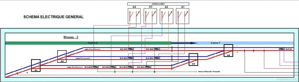
See the diagram of level N-2 below.
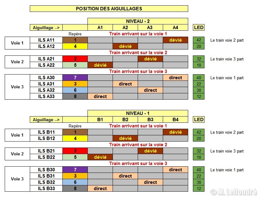
1) - when the first train enters Track 1, it activates ILS A11, which deflects switch A4, freeing the train parked on Track 2, then activates ILS A12, which deflects switch A2 and stops;
2) - the second train, having completed its journey, enters Track 2 due to the orientation of switch A2 controlled by the previous train; it activates ILS A21, which deflects switch A3, freeing the train parked on Track 3, then activates ILS A22, which deflects switch A1, and stops;
3) - the third train, having completed its journey, enters Track 3, activating ILS A31, which sets switches A3 and A4 to the right position, freeing the train parked on Track 1, then activates ILS A32, which sets switch A1 to the right position, and stops;
NB: If I use the slides on level N-1 in the same way, and knowing that my circuit has 4 blocks, I can run 7 different trains alternately (3 running trains + 4 parked trains).
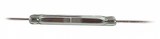
ILS
(Soft-blade switch)
Placed between the rails, it makes contact when the magnet under the locomotive passes over it, enabling the points (or block power supplies) to be controlled.